Posts

Showing posts from December, 2020

Abaqus basic information

Image
hi Abaqus students. In this post, I will share with you the basic things I know about Abaqus software. 1. First level unit consistency and conversions Mass Length Time Force Stress Energy Density Young's Modulus Gravity Kg m s N Pa J 7.83e+03 2.07e+11 9.806 Kg cm s 1.0e-02N 7.83e-03 2.07e+09 9.806e+02 Kg cm ms 1.0e+04N 7.83e-03 2.07e+03 9.806e-04 Kg cm us 1.0e+10N 7.83e-03 2.07e-03 9.806e-10 Kg mm ms kN GPa kN-mm 7.83e-06 2.07e+02 9.806e-03 g cm s dyne dyne/cm^2

abaqus animated views

Image
hi Abaqus students. We will see how to get an animated result view in Abaqus software in this post. animated result view is the visual form of the job we created. When the job we have created is submitted and completed, click on the resulting menu. After clicking on the resulting menu, the visualization page appears. In this visualization page, in the side menu icons, click on the icon contours on the deformed shape and then the animated time history icon. Then click on the animated menu in the top menu bar on the visualization page. After clicking on the animated menu, click on save as Potton in the new tab that appears below the animated menu. In the new tab that appears after clicking save as Potton, click on the folder icon next to the file name box and select the correct folder. Then change the format box from AVI to QuickTime.Finally, click on ok at the bottom of the tab and our animated view is saved.

abaqus cross cut view

Image
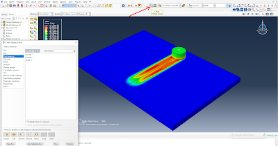
hi Abaqus students. We will see in this post how to get the results we got in Abaqus software in cross-cut view. When the simulation analysis is completed, click on the resulting menu. After clicking on the resulting menu, the visualization page appears. Click on the plot contours on the deformed shape icon in the side menu icons of that visualization page. Then click on the view cut manager icon in the side menu icons. If you tick any of the tick boxes in the x, y, z tick box in the new tab that appears after clicking on the view cut manager icon, the cross-cut view will appear in the result part. You can resize the cross-cut view by changing the position at the bottom of the tab. Thus we can calculate the extent to which the study we have carried out has had an impact on the interior of the object by obtaining a cross-sectional appearance. For example, in Abaqus software, if an object collides with another object and is studied, the

abaqus run time reduce

Image
hi Abaqus students. We will see in this post how to reduce the extra time for analysis in Abaqus software. If we want to perform simulation in Abaqus software in dynamic explicit mode or dynamic temperature displacement explicit mode it can sometimes take a long time to complete the simulation analysis run. This sometimes depends on the processor used in the computer. Try the following methods to reduce the extra time thus taken. 1) The rigid part can be used in the analysis. 2) Material properties units must be consistent. 3) Very short duration can be used in the step. 4) Try fixed time (user-defined time increment) in step incrementation. 5) Mass scaling can be used step by step. 6) You can increase the interval size in the field output request. 7) Can be used to reduce the amount of friction in interaction. 8) Surface to surface contact can be used extensively except for general contact. 9) Select t

abaqus rigid body

Image
hi Abaqus students. We will see how to do the rigid parts in Abaqus software in this post. The rigid part is like a very hard structure. This method can be used for a system such as the general tool of simulation. This rigid part can be created in two ways. The first method is to create it in part creation using discrete rigid or analytical rigid. But if we create a rigid part in this way, we will not be able to give any material properties to that rigid part. The second way is to make the part deformable in part creation and give the constraints for the rigid body in the interaction section. You can also use the material properties to create a rigid part in this way. To implement this method you need to place a reference point on the rigid part (tool> reference point). If you give a name to this reference point, you can use that name when giving a constraint manager and boundary condition. This can be done by selecting the reference poi

abaqus parts remove and add

Image
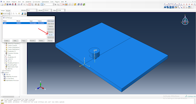
hi abaqus students. We will see in this post how to remove and add the parts we have created in abaqus software.When we are working on abaqus software we have to give surface to surface contact to two or more objects that are very closely fitted in the interaction section.Or if two or more parts are used in the simulation work and you want to get only the result of one particular object in it, you have to remove the other objects.In such situations the parts remove, add option can be useful. We must first enable display group icons.For that you need to click on the view menu in the top menu bar.After clicking on the view menu, a new tab will appear below the view menu. Move the cursor towards the toolbar menu and click on the display group menu.After clicking on the display group menu, new icons for the display group appear on the main page. Click on the create display group icon which is the seventh of these icons.Clicking on this icon will create

abaqus step by step frame view

Image
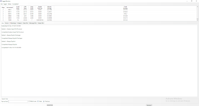
hi abaqus students. We will see in this post how to view the results available in Abaqus software frame by frame. In some cases, the simulation we worked on in Abaqus software may take longer to complete. In such cases, we can use the step by step frame view to know if the simulation we have created is heading towards the right goal. When we know this, we can make the necessary changes as soon as the simulation we have created moves towards the wrong destination and continue the test again, thus saving a lot of time. To do this we need to create and submit the simulation and monitor the run on the monitor for a few seconds. Thus the simulation we have created should run for a few seconds and then click on the resulting menu and the visualization page should appear. Click on the plot contours on the deformed shape icon here. Now click on the resulting menu in the top menu bar on the visualization page (result> step/frame> apply). Now click on the step/f

abaqus parts colors code

Image
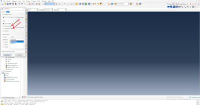
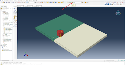
hi abaqus students. In this post, we will see how to give color code in Abaqus parts. To give color code in Abaqus you first need to enable the color code menu bar. For that go to the assembly section in Abaqus and first click on the view menu in the top menubar. After clicking on it, a new mini tab will appear below the view menu. Now move the cursor to the toolbar menu in the new tab and click on the color code menu to enable it (view> toolbar> color code). Once done the icon for the color code will appear on the main page of the assembly section. Now you need to click on the icon for the color code. After clicking on the icon for the color code, a new tab will appear. In that new tab, change the color code by the box from assembly defaults to parts option.If changed in this way the default color in Abaqus will be given to the parts.We can give the desired color to the parts by clicking on the color symbol in the center of the tab and then by clicking on